Tuesday, September 7, 2010

LED (Light Emitting Diode) Dynamic Microphone

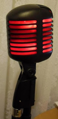
The Finished product, when you're not using phantom power the microphone works as normal and still looks 100% like it just came from the Shure factory. Hit the phantom power switch and the mic glows with a strong presence.

For a few $$$ and about two hours of your time its a great mod that will work on any Balanced Dynamic Microphone. The results and accomplishment are really worth the small amount of effort needed to complete the project.

Happy modding!


note: we take no responsibility for you damaging your microphone in any way shape for form! Mod at your own risk!

Installing the LED frame


Attaching our new frame should be relatively easy, however the check that it fits (even if the checked earlier), the mic below had to have each side (left & right) of the frame trimmed back a little to make it fit better. if you have to do this take great care as the more you take away the thinner your frames sides become and more fragile.

although you cant see it, in the frame below we used some clear five minute epoxy on the sides of the frame to give it extra strength and to insulate the exposed LED leads just in case to ensure no 'short circuits'

what you cant see in the picture below is that there are fiber washers under the frame of each of the two bottom screws to keep the frame at an even level. do not use metal washers as most balanced dynamic microphones are chassis grounded & you dont want that washer coming into contact with any other solder pads or components.


note: we take no responsibility for you damaging your microphone in any way shape for form! Mod at your own risk!

Mounting the LED’s

Once our frame is ready, start by drilling the holes in each corner to mount the frame to the mic chassis, and then determine the best position for each LED. For better and more even results, mount one LED in the each corner of the frame on each side, being four LED’s on the front & four LED’s on the Back. They don’t need to be in exactly the same position but close enough is good enough.


The frame in the example has ample room to mount the four 1w resistors, its important that they be placed somewhere that wont come in contact with anything else as they may dissipate some heat (if any). Looking at the schematic the best way to mount the resistors is the stack one on top of the other, wrap one resistors leads around the other and then solder them together so they are connected in parallel. This is ensure you will have a secure mount with only one lead at each end of the resistors to solder to the circuit. You can mount the components anyway you like, however with the limited room inside the mic chassis this seems to be a good spot.


When mounting the LED’s you can use each lead to join each LED together, use the holes in the protoboard & if need be gently twist each lead together with the next LED in series for extra support.


After you have connected the circuit and soldered in the LED’s the next step is to connect the ground wire, the best place is directly to Pin 1 of the XLR connector (main ground). If you cannot do this then find a good place that the chassis of the mic will allow you to ground the circuit like a mounting screw. In the picture below we soldered a ‘Solder Ring’ above one of the mounting holes in our frame so that when its screwed down the screw will make contact with the chassis (that is connected to Pin 1 of the XLR) closing our LED circuit.


The only thing left now is the solder two small wires from the resistors to the microphone circuit (Pins 2 & 3 of the XLR connector)


Before you put your frame in, test the circuit with an XLR cable to ensure it works. If testing is good then you can use some epoxy to cover the exposed LED leads & tracks for two reasons. To ensure your solder connections don’t come detached over time and to insulate the exposed leads so they don’t come into contact with the foam windscreen.

Finally mount the frame to the mic chassis & solder the two wires to the XLR connector (pins 2 & 3). In the Super 55 the solder pads make this easy.


Take great care when mounding the LED frame & ensure it does not come into any contact with the mic element.


note: we take no responsibility for you damaging your microphone in any way shape for form! Mod at your own risk!

Monday, September 6, 2010

LED Test Circuit

Before we start to mount anything, we are going to make a test circuit to ensure everything works. Phantom Power is no joke and 48vDC is enough to instantly kill your LED's in a split second.

Below is the schematic diagram that outlines the circuit, We are connected all eight LED's in series and using four resistors to get a total working voltage of about 1.8v & a current draw of just under 30ma. Phantom power does not offer much current at all, however with the resistor network in the diagram we can safely draw a stable 30ma of current from phantom power without damaging most modern mixers or phantom power boxes.

Note: depending on the spec of the LED's you're using you may have to calculate different resistor values, however for a 30ma current draw and a forward voltage of roughly 1.8 volts the resistor network in the diagram below will work as long as you have eight LED's and you stick to the schematic.


Below is a test circuit, no matter how ghetto your test circuit is we want to ensure it works correctly. The main issue we are looking for is how much heat the resistors will dissipate, my circuit only raised 1 degree Celsius from room temperature after running for more than two hours strait and to the touch there was no noticeable difference in temperature.


Click on Each Image for a Lager View

The circuit is designed for the LED’s to be connected in ‘series’ & for good reason. With the small current, we can draw from phantom power we need to keep the current drain requirements to a minimum. Connecting LED’s in series allows for the same current that one LED would require lighting all eight up whilst dividing the supply voltage each LED.

If you plan to connect the LED’s in parallel, Do Not do this as each of the eight LED’s will draw there set current individually. Therefore, if we have eight LED’s in parallel each taking 30ma of current the total amount of current drawn would be 240ma, which is excessively much for your phantom power to handle and could damage your phantom power supply. The only advantage of connecting LED’s in parallel is that the supply voltage is not divided between each LED, so each light will receive the same supply voltage

note: we take no responsibility for you damaging your microphone in any way shape for form! Mod at your own risk!

Template to Reality (LED Frame)

Once we have our template cut to the correct size its time to transfer to a real frame, in my mic i used perfboard (prototype board). The proto-board used is the stuff that does not have any copper pads or traces on it as we don't need it and want to keep a minimum of metallic parts that could accidentally short out the circuit.

This stuff is cheap and strong, but its wining benefit is that protoboard can handle heat from the energy that may be dissipated from the LED circuit. The easiest way to cut this stuff with basic tools it to first have a nice flat strong service to work on, get your template and trace it over the protoboard. With a sharp blade and a lot of care run the blade along the traced lines to make an indent in the protoboard.

If you have a a small drill bit (2mm) drill out each corner of the traced frame, then take a hammer, small chisel & slowly with great care cut out the frame.

Once the frame is cut out take a flat file and file down any sharp edges and try to make all edges/corners smooth to the touch. once you finish you should end up with something similar to the picture below.

Photobucket

note: we take no responsibility for you damaging your microphone in any way shape for form! Mod at your own risk!

Making a frame for the LED's

The first thing we need to do is find a way to mount the LED's so that they can be positioned in the best place possible. To get really bright results we will need to mound 8 (eight) LED's inside the Shure 55 shell, this means that there will be four in each corner front & back.

Looking at how the microphone cartridge is mounted, the best way is to make a frame that can be bolted on top of the existing structure. Firstly measure the mounting holes distance from each other and determine how much space you can take up without touching the mic cartridge.

The best way is to use a thick piece of cardboard as a template, you can trim it as you go to ensure it fits perfectly.

Photobucket

note: we take no responsibility for you damaging your microphone in any way shape for form! Mod at your own risk!

Inside The Shure Super 55 Mic

The Shure Super 55 Dynamic Microphone has a classic case, however, the microphone has a modern Dynamic Cartridge. Shure didnt just put any cartridge in the Super 55, they opted for the "Beta 58" Element. Its the Hod Rodded version of the industry standard SM58 microphone with an extended frequency response and a Super Cardioid pickup pattern for higher gain before feedback with a more focused sound blocking more instrument/stage bleed from the sides.

Having an updated dynamic cartridge is a bonus for us as it gives more room to find a way in mounting the LED's.

From the Picture below you can see that there really isn't much to the microphone, its a dynamic element going into a mini transformer then a small circuit board. There's actually only two connections made with XLR cables for balanced dynamic microphones, pins 2 & 3 as the ground pin is only connected the the mic chassis.

Photobucket

note: we take no responsibility for you damaging your microphone in any way shape for form! Mod at your own risk!

The Dynamic Microphone (Shure Super 55)

The Special Edition Shure Super 55 Dynamic Microphone.

A classic icon that never seems to die, if you talk about microphones to the average person they're more than likely to be thinking of the Classic "Elvis" Style birdcage mic's. and if you type 'microphone' into a search engines images a Shure 55 will pop up within the first ten results.

This Blog will Teach you how to add that extra touch for a lively stage performance with your Shure 55 series microphones, add some LED's (lights) to your mic and run them from phantom power safely and securely for the ultimate impact at your next gig.

This is the Special Edition mic from Shure, the regular mic is silver with a bright blue foam wind screen, however this mic's colour scheme speaks for it's self!

Photobucket

note: we take no responsibility for you damaging your microphone in any way shape for form! Mod at your own risk!